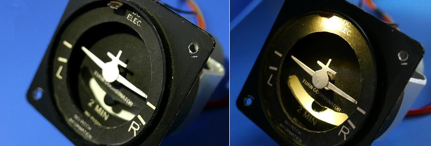
Turn coordinator
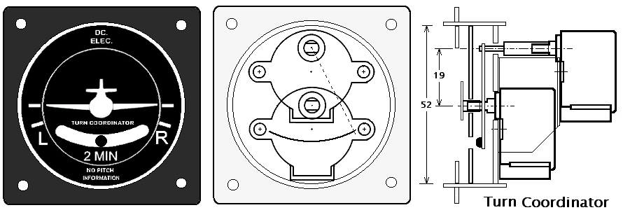
Two stepper motors
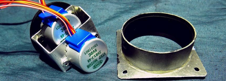
I used Two stepper motors for the two indications of 'turn rate' and 'turn balance'.Arranged by shifting it back and forth so that it fits inside the inner diameter of 52 mm. He used a 1mm aluminum plate for the frame that holds the motor in place. Make a paper pattern from paper, check the position, etc., and then cut the aluminum. If you do not consider the bending order, it will be difficult to process with a vise.
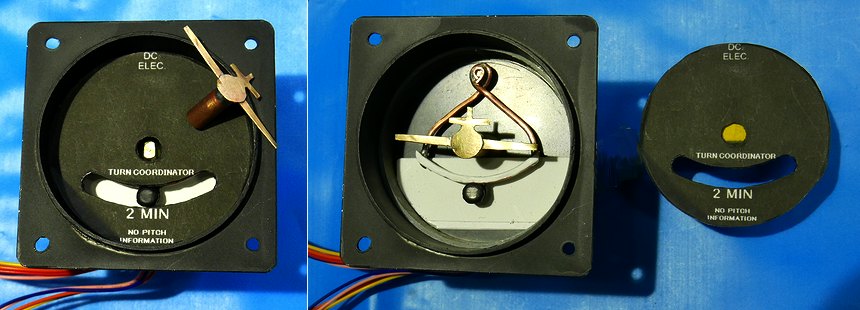
The extension of the motor shaft is made by rolling a brass plate and fitting her into this pipe. A copper plate is also wrapped around a 3mm brass rod and soldered to the inside of the pipe. Since the rotation angle is as small as 60 ° or less, even a slight eccentricity will have no effect. Consider that it just fits tightly and doesn't fix it to the motor shaft because it disassembles. Also, don't break it even if I turn it too much due to a mistake in the program.

config setting
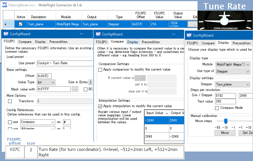
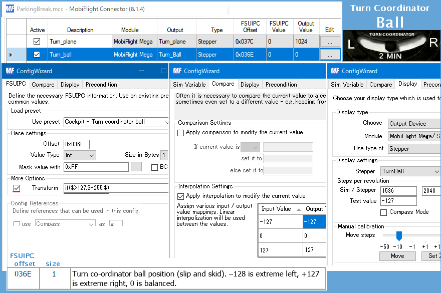
Mobiflight's Config adjustments are progressing little by little.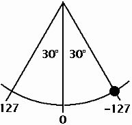 There is a little ingenuity in moving the Ball. The data from offset 0x036E of FSUIPC needs to be processed as follows.
If ($>127, $-255, $) --- If the current value is $>127, set it to $-255, otherwise set it to $.
Since AutoZero returns the pointer to the position where the value is 0, set it so that it will be in the fixed position when $ = 0 when converting the value.
The sim/stepper column of Steps per revolution was set to 1536 / 2048. This outputs 128 sims to rotate 30°, so 128×360/30=1536 is used to rotate 360°. Also, if the auto Rudder setting is not turned off in MSFS/FSX, It will not move because it will be automatically controlled.

Lighting
I installed lighting with white LEDs. The Ball part is illuminated from the bottom inside, and the Plane part is illuminated from the front top.