Yoke
Control by Leonardo
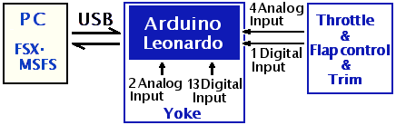
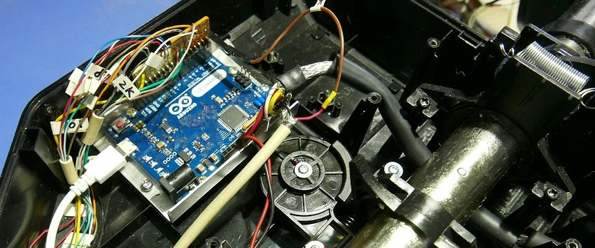
York does not use Mobiflight, but uses Arduino Leonardo with an analog input Sketch. Throttle and flap controls are also connected here. It replaces the original Saitek yoke electronics.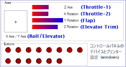 Arduino Leonardo is programmed with 6 analog inputs and 14 switch inputs.
 Only 9 out of 14 switch inputs are used, such as 4 for the hat switch, 1 for the parking brake, and 2 for changing the viewpoint.
The analog input may pick up noise and the input value may fluctuate. Therefore, a ceramic capacitor is between it and GND, and the variable resistor is protected by a net wire shield.
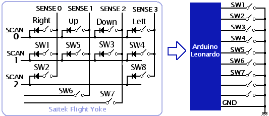 The original Yoke switch input is a detection matrix, but it will be replaced with a simple switch with GND. The wiring will be easier to understand. No diode is required.
 However, I don't need so many switches in the yoke. It is more convenient to attach a switch to the cockpit panel for operation. I would like to install a lot of switches on the panel in the meantime.
Chenge spring
The spring for centering the yoke is too strong, so I removed one of the two Y-axis springs inside. I removed the X-axis spring and replaced it with a softer pull spring. Now the operation is much better.I am considering expanding the X-axis rotation angle of the yoke to 45° on both sides. This will require a modification from the current linkage to a different mechanism.
Yoke2_Wood
Wood handle
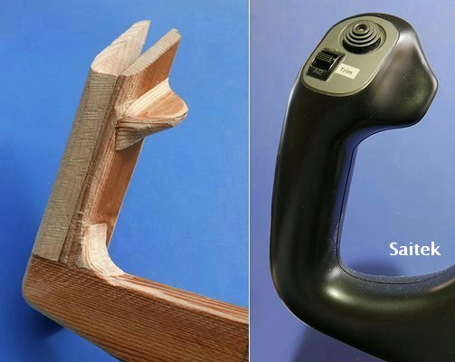
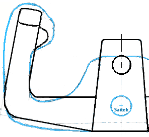
I made the Yoke handle of wood.One of the reasons I tried to remake the handle of Saitek Yoke was that I had this grip too thick. Another thing is that there is wobbling due to the thin plastic between the handle shaft. I don't like the shape of Yoke, I don't need a clock in the center of the handle, and I wanted to make it more neat.
The thickness of the grip is
・ Saitek Yoke has a depth of 43mm and a width of 35mm. I felt that this was a little thick.
・ In the TOYOTA car Porte, It's handle is thin with a depth of 34 mm and a width of 28 mm, which is probably decided considering the size of his hand so that I will not get tired even if I keeps holding it.
・ The self-made Yoke has a depth of 36mm and a width of 28mm, which is close to the thickness of a TOYOTA car.
Only a few switches are installed here. If I need a switch, I can attach it to the operation panel with a label.
I considered metal pipes and PVC pipes as materials, but bending is difficult. That's why I made parquet with wood that is easy to process. The part where the force is applied is fixed with mesh and wood screws.
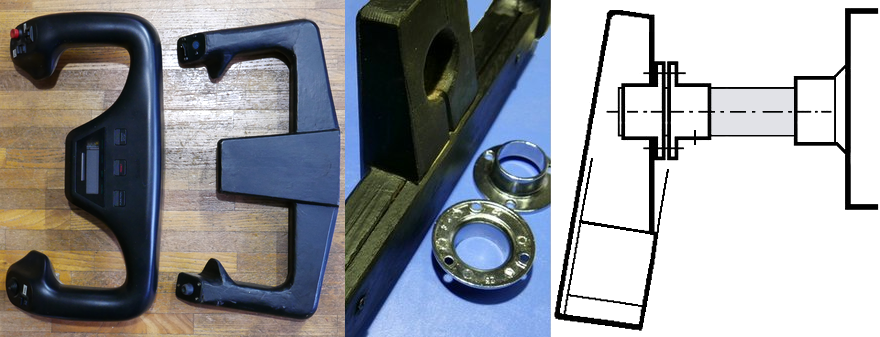
 A groove is dug inside before laminating the wood so that the switch wiring can pass through. I also considered that the wiring can be replaced and inspected and repaired.
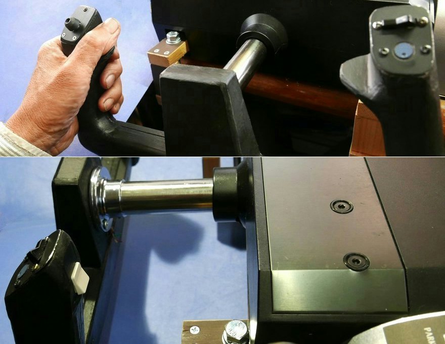
 The shaft of Saitek Yoke is a metal pipe with a diameter of 25.0 mm. Since this is 25.0 instead of 25.4, I can use a commercially available 25.0mm pipe socket without having to make the fixing bracket from scratch. When I put it together, it was a little hard to fit, and I could fit it more firmly than I expected. This will vary from manufacturer to manufacturer. It is doubled to fix it firmly. I also attached a set screw.
Compared to Saitek's Yoke, the shaft mounting position is slightly higher. The height of the shaft is about the same as the height of the hand. This makes it easier to return to the center position because the Yoke body is placed on a desk and is at a height that is easy to operate, and the center of gravity of the entire Yoke handle is below the axis.
(The handlebar axis of Saitek's Cessna Yoke was 25.4mm. There may be differences depending on the time of manufacture.)
Widen the angle of rotation
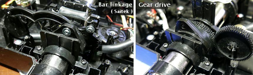
The rotation angle of Yoke X-axis is limited to 90 °, but I have been modified so that it can be rotated to an angle close to the actual airplane.The original configuration uses a link mechanism to the variable resistor. Since it is difficult to rotate 180° as it is, I decided to incorporate a gear instead of a link mechanism.
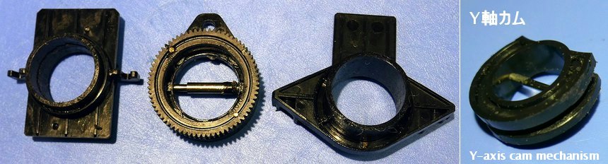
 The part with the spring of the X-axis centering was removed to make space, and instead a gear with a large hole of 31 mm was installed in the center. I attached it to the link mechanism on the front side with a 2mm screw.

 I searched for spur gears that could be used, but for the time being I found RC car parts. Reference circle diameter 42mm 71T Module0.6. I also searched for a smaller gear that fits this. Most of the parts of the same TAMIYA have no standard written on the label or the materials on the site, whether they are spur gears of the same module, so there is no choice but to check the actual teeth together. Originally, it seems that it is a repair part corresponding to each kit. Gears of various modules are mixed.
 Gear 61T is used on the variable resistor side.
This results in a yoke handle rotation angle of 180° X 71/61 = 209° (variable resistor VR rotation angle).
 The rotation of 180 ° cannot be achieved only by modifying the gear. The cam to the Y-axis control supports up to 90° and stops halfway. The metal rod that supports the central shaft was pulled out once to shorten it, and the groove on the side was extended and dug. I made a stopper on the Y-axis cam that limits the X-axis rotation, but it can still rotate up to 250°. The software sets it up to 180°.
 Now the X-axis Roll can be operated very smoothly.
Yoke3_Cessna
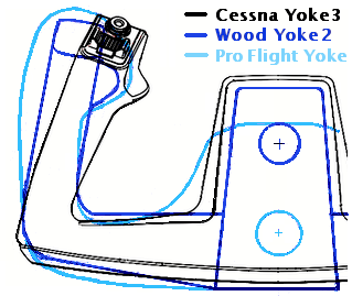 I have begun work to replace the handle of Cessna Yoke with a homemade wooden handle.
A spring is used for centering on the Cessna Yoke, but I don't like this, and I'm concerned that there is some play in the movement near the center. Therefore, I decided to take advantage of the internal mechanism that I had constructed because it worked much better. I am replacing the Yoke main body control board with Arduino Leonardo. There are controls other than Yoke here, so I'll make use of this as well.
I can use analog input using Mobiflight, but if I set Leonardo as HID (Human Interface Device), I can make detailed settings while viewing the input curve graph with MSFS2020 Joystick AXIS.
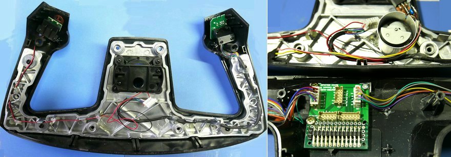
The Cessna handle was unexpectedly improved. A die-cast frame is attached to the inside of the plastic, making the whole thing sturdy and heavy. A connector is used at the shaft so he can disconnect the cable. Since this connector is 2mm pitch, I made a board to convert it to a 2.54mm pitch connector. There are just too many input switches. In my environment, switches are usually installed on control panels, so I'm thinking of organizing them and reducing them a bit.
Installing the vibration motor
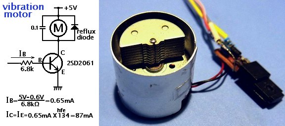 A cover was attached to surround of the vibration motor so that the wiring inside the Yoke would not come into contact with it. Maximum driving current value is 170mA
Instead, I considered a circuit to limit it to about 80mA. This is enough for vibration.
When I measured 2SD2061, hfe=134, so the base current should be 0.6mA. Actual measurement showed that Ic=84mA was flowing.
A cover was attached to surround of the vibration motor so that the wiring inside the Yoke would not come into contact with it. Maximum driving current value is 170mA
Instead, I considered a circuit to limit it to about 80mA. This is enough for vibration.
When I measured 2SD2061, hfe=134, so the base current should be 0.6mA. Actual measurement showed that Ic=84mA was flowing.
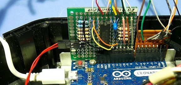
Use 74HC165(Shift register) to increase input ports
 I think only need about half the number of switches that CessnaYoke has. Moreover, the Arduino Leonardo doesn't have enough I/O to use all the switches.
 I'm trying to figure out a way to increase the number of I/Os on Leonardo, even though I know it's not necessary. It's interesting to come up with countermeasures and sketch Arduino.
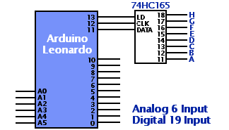
74HC165 is used to increase the number of I/O ports. With Mobiflight, I can do it right away, but to use Leonardo with HID, I need to think of Sketch myself.
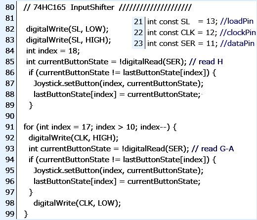 I looked for a program that uses Arduino Leonardo's HC165 for switch input, but I couldn't find one that could be used as is, so I created the part that takes in the input like this. It is configured and used based on the publicly available Joystick Library.
The function ShiftIn() doesn't work, so the first half reads input H, and the second half reads input G~A.
 Now I can use so many switches. I've started assigning functions little by little, but I wonder if I'll be able to use them all.
I'm currently experimenting with various assignments, focusing on changing the viewpoint rather than operating the aircraft.
Now I can use so many switches. I've started assigning functions little by little, but I wonder if I'll be able to use them all.
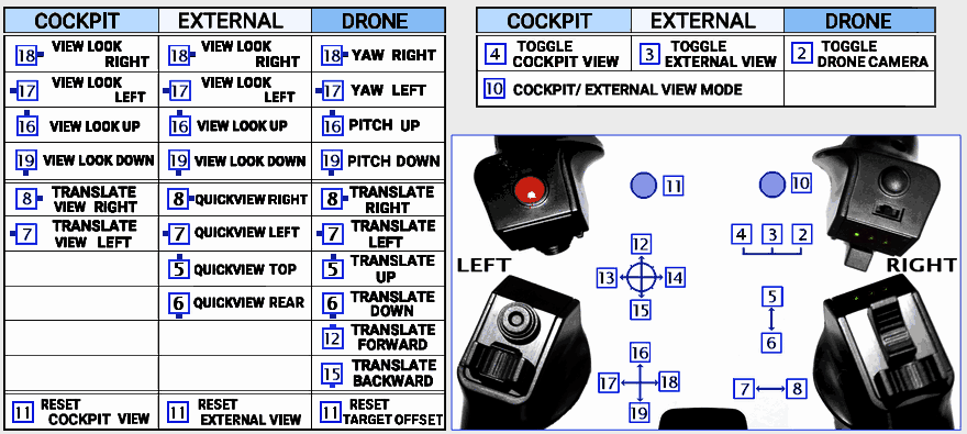
I'm currently experimenting with various assignments, focusing on changing the viewpoint rather than operating the aircraft. If I use a hat switch, I can input in 8 directions, but I haven't set it that way. Also, the port numbers for Arduino I/O are 0~18, but for MSFS they are 1~19. This figure is based on the MSFS Control Settings.
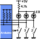 It was a pain to switch camera modes using the on-screen toolbar, so I assigned it to a switch. Camera mode is changed by switching sw4,3,2. This switch is a slide switch, but it can be used by assigning settings.
 There are 3 LEDs near this slide switch that indicate switch position. Modifying the original circuit board, I created a circuit that would light up an LED when the switch was turned on. This will make it easier to locate the switch lever. Since it is a slide switch, only one of the LEDs lights up, and there is only one current limiting resistor.
List of Camera settings
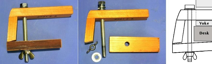
Clamp
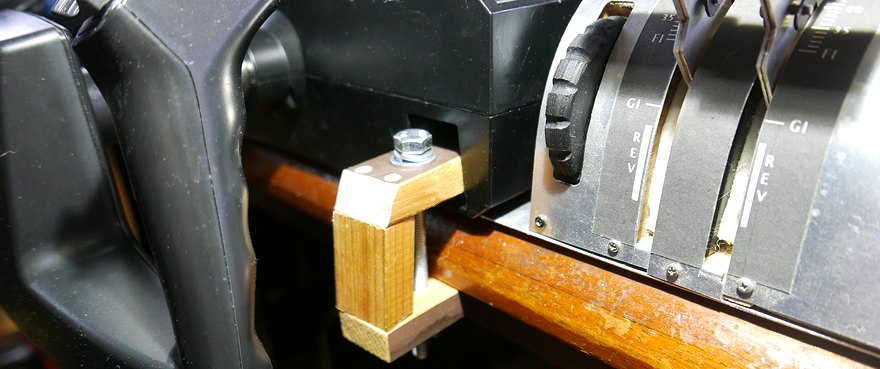 This is the clamp that attaches Yoke to my desk.
 I couldn't use the Saitek one to attach it due to the structure of the desk, so I made two wooden clamps. The structure is simple, but the Yoke handle is shaped so that it won't hit when handle push it in. The bottom plate of the throttle on the right fits under the Yoke, which also serves to secure it so that it does not move.