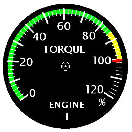
Torque meter
Torque meter(old version)
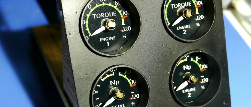
I am making a torque meter to know the condition of the turboprop engine.A reciprocating engine requires a meter in RPM with a tachometer, It seems that the standard requires turboprops to be equipped with a torque meter for propeller output for output control.
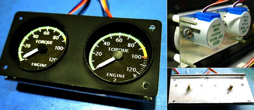
This meter is a pair of left and right instruments for twin-engine aircraft.
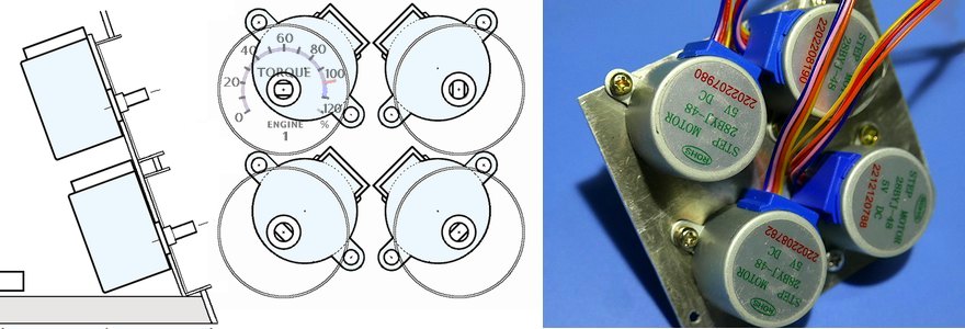
The meter case used to have an outer diameter of 54 mm, but this instrument was planned to be slightly smaller and have an outer diameter of 43 mm.
Based on a 54mm pipe made of vinyl chloride, it was softened with hot water slightly over 60 ℃ to make a pipe with a diameter of 43mm.
The two motors don't fit in this, so he tried to pinch the panel from the front and back.
Engine Tachometer(RPM)
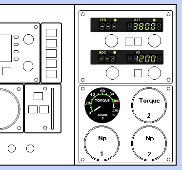
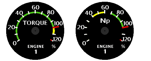 I'm planning to add one more instrument for the turboprop engine.
It's a tachometer.
I'm planning to add one more instrument for the turboprop engine.
It's a tachometer. The torque meter will also be relocated from its previous position.
The size of the meter is slightly smaller to show the status of the left and right engines.
I tried to see if I could configure it with a servo motor that I had never used before. SG90 seems to be used a lot. However, this only rotates 180 degrees (SG90HV rotates 360 degrees, but it seems that the rotation angle cannot be controlled).If it is a radio-controlled rudder control, it can be less than 180 degrees, but it cannot be used for a meter. If I add a 1:2 gear to the output of the SG90, I can rotate it 360 degrees, but setting up 4 pairs of gears is too much work.
I decided to use the usual stepper motor.
The space between the four stepping motors is so narrow that there is not enough room.
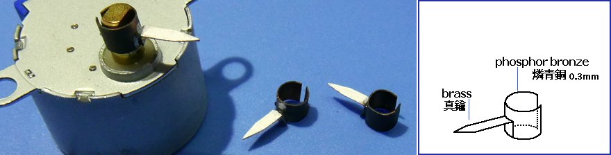
 The meter pointer is not fixed, but fitted in to make it easier to disassemble and adjust. The phosphor bronze plate is elastic like a spring and is held in place. The pointer is made of brass and attached by soldering.
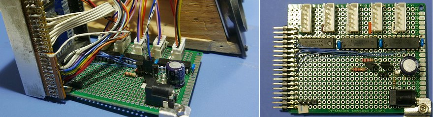 ArduinoMEGA2560 is placed on the back and includes driver ICs for four step motors. I installed a connector for auxiliary power.
 The fifth connector on the far right is for the stepper motor used for the RMI display.
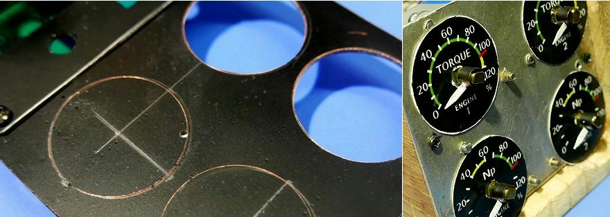
 The small craters on the surface of the panel are the remains of 1mm holes drilled into the etched base for the original circuit board. I've filled most of it, but there's still a little left. Glass epoxy is not more difficult to process than plastic >PS-HI< , and it is also very strong.
 Attach a small piece of black paper to the top of the center of the meter axis.
Meter lighting
This is the meter lighting that I thought I had to do someday. I have installed LEDs on compasses and other devices, but I also installed LEDs on four engine-related items. The white flat LED I used was disassembled from a broken 40W LED straight tube. The base with the LED is cut slightly diagonally so that it faces inward. It's a small meter, so there's only one of each.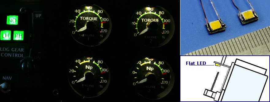
Settings
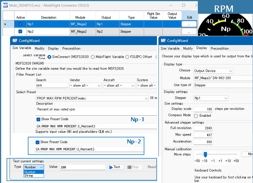
With Mobiflight 10.0, some settings screens have changed. There are some things I don't fully understand, but for now.You can choose from SimConnect's Presets, but if you enter torque in the Search field, it will narrow it down to four. This is convenient.
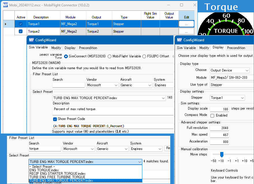
RPM settings. Under Show Preset Code, specify Engine 1 or 2. Also, in the Test current setting, the pointer hardly moves at the initial value of 1, so try setting it to around Number 100.