Radio Magnetic Indicator
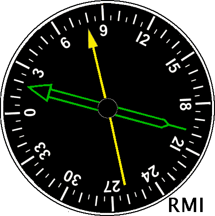
I am planning to build RMI(Radio Magnetic Indicator). I am starting by researching the documentation and understanding its functions.
VOR indicates the direction of an aircraft as an angle to magnetic north as seen from a radio beacon station.
VHF Omnidirectional Range (VOR)

Setting
I've tried looking at the settings available in Mobiflight from the FSUIPC list.The RMI pointer needs the relative angle to the compass, so the following might be useful:
・0x0C56 NAV1: relative bearing to VOR1, in degrees (0–359)
・0x0C6A ADF1: relative bearing to NDB ( *360/65536 for degrees, –ve left, +ve right)
NDB (non-directional beacon) is a medium wave non-directional radio beacon, the direction is detected by ADF.
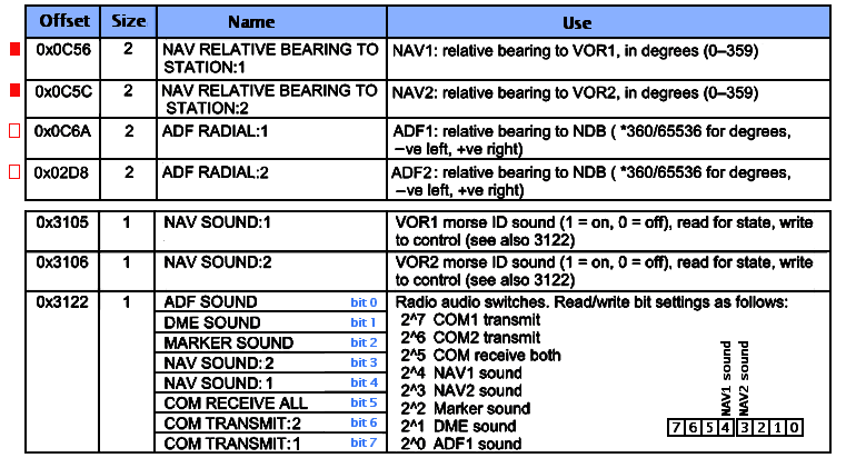 I heard that VOR stations also transmit their station names in Morse code, but I wonder if it's possible to set it up so that I can hear the morse IDcode sound. I've practiced telegraphy with my radio operator license, so it would be fun to hear it.
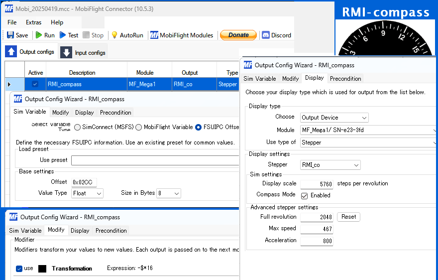
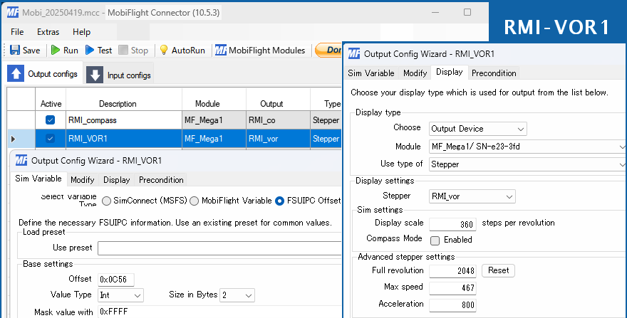
RMI Structure
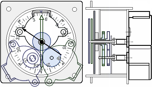
 The compass, green needle, and yellow needle rotate on the central shaft. It is necessary to transmit the rotation from the two stepping motors placed next to each other to the central shaft using spur gears to make them coaxial. Combine the spur gears to connect the gaps between the motor shafts and overlap the rotating shafts.
Also, with this arrangement of three motors, the protruding parts will not fit through the holes in the panel when installing. I plan to separate the panel surface and the motor part and assemble them from the front and back.
The gear axis and motor axis will be in a straight line, but with my machining precision it is very difficult to align three axes at the same time. Therefore, the connection point with the motor axis will transmit rotation to the gear axis via a simple universal joint. The connection is made with a 1.2mm brass rod, and the structure does not get in the way of disassembly and assembly. Step motors have a lot of torque and do not rotate very fast, so this mechanism works.
 To control three motors, 4x3=12 Arduino output terminals are required. Therefore, Arduino MEGA2560 no.1 will use the terminals for two old Toque motors that are no longer needed. In addition, MEGA2560 no.2 has many spare terminals, so I plan to connect another stepping motor there. There are also spare terminals for the motor driver ULN2003 here.
Remaking the gear mechanism
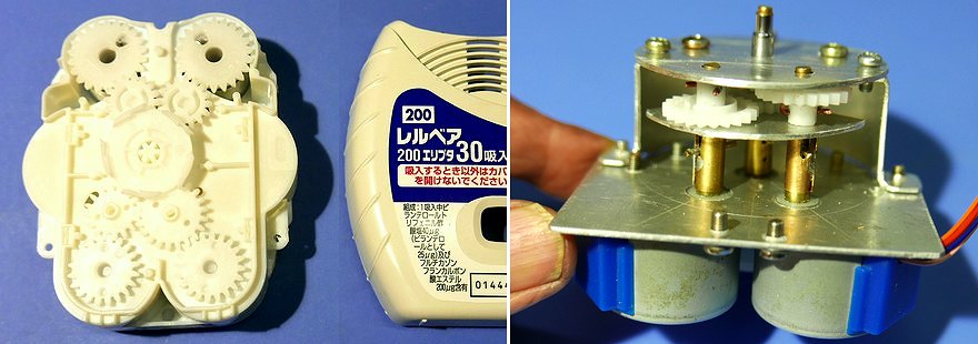
I was using 22T and 20T gears, but when I corrected the rotation angle of this gear ratio, the compass mode in the Mobiflight settings did not seem to work properly. I couldn't find a solution, so I was thinking about addressing it on the hardware side rather than the software side.I went to the respiratory medicine department and was prescribed inhaled medication again. It was the same medication as last time. I took the opportunity to disassemble the inhaler I had finished using and get the gears again, so I replaced the RMI gears with a 1:1 ratio. As the gear diameter had increased, I decided to widen the shaft spacing from 15mm to 17mm and rebuilt the entire mechanism.

Installation on Panel
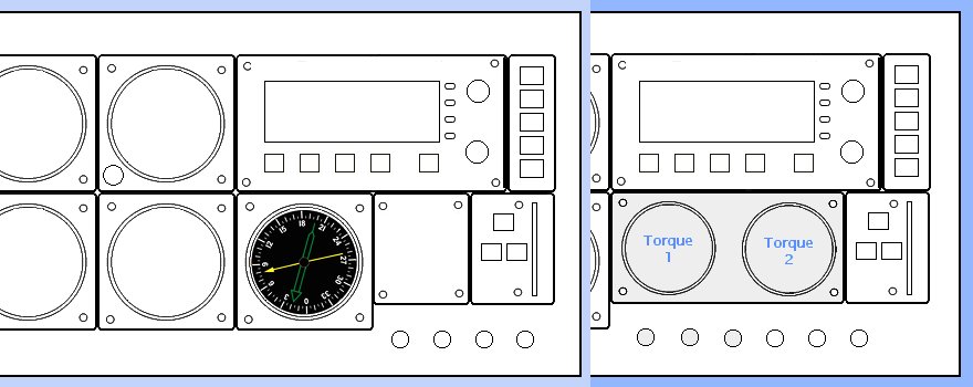
 RMI was installed where the old torque meter was. It cannot be installed without removing the switch. There is now a gap between the right wheel storage lever switch and the RMI, but I'm thinking of installing some kind of display there as well.
VOR station
Some VOR stations have disappeared, and their frequencies and IDs have changed. This list is based on data from the Ministry of Land, Infrastructure, Transport and Tourism in 2003, with subsequent revisions.However, there is another issue: what point in time the VOR station data is reflected in MSFS2020.
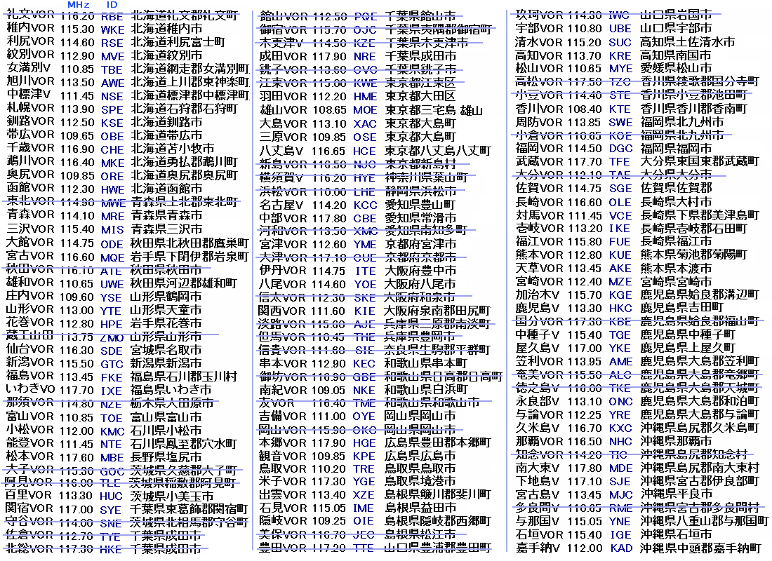 The third letter of the VOR station ID is E if a DME is installed. The third letter is C if a TACAN is installed.
I went to see it for myself. The Otsu VOR station at the summit of Nyoigatake is no longer transmitting radio waves. There was a large structure covered in plants. This appears to be an antenna counterpoise (one of the antenna grounds).
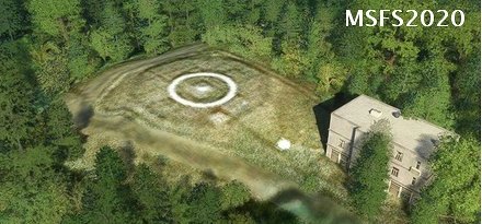 The circular steel structure of this VOR station is barely visible in MSFS, but what I see on top of it are white VHF transmitters lined up in 48 directions connected in a ring.
VOR determines direction by the phase difference between a reference phase signal and a variable phase signal. The main carrier wave is omnidirectional, but the variable phase signal is generated by scanning many directional antennas arranged in a circle.
I can zoom in a little more on this structure on Google Maps.
(Both show the Otsu VOR station.)
 The circular steel structure of this VOR station is barely visible in MSFS, but what I see on top of it are white VHF transmitters lined up in 48 directions connected in a ring.
 VOR determines direction by the phase difference between a reference phase signal and a variable phase signal. The main carrier wave is omnidirectional, but the variable phase signal is generated by scanning many directional antennas arranged in a circle.
I can zoom in a little more on this structure on Google Maps.
(Both show the Otsu VOR station.)

