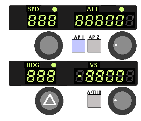
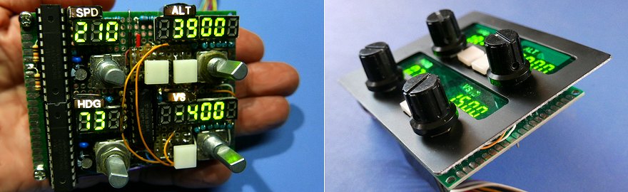
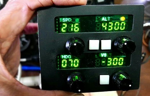
AutoPilot (Flight Control Unit)
The A320-type autopilot FCU is designed and constructed in such a way that it is easy for me to use. It's quite difficult to concentrate on setting and operating equipment, so I am proceeding with production little by little.
I didn't fully understand how the controls and switches worked, but I started making them. If there is something missing, it should be improved or modified.
Unlike Airbus equipment, which is lined up side by side, it is divided into two rows, one above the other. It's compact enough to fit next to my control panel.
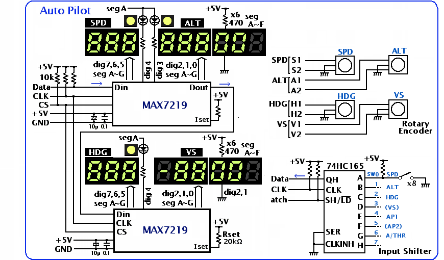
Two MAX7219 are used. The 7-segment LED is the same small yellow-green LED used for digital ALT.
It would be easy to use the LEDs completed as the MAX7219 module, but I wanted to avoid the red color as it is a warning color. It takes a lot of wiring, but it's a fun way to make something I like.
ALT enter at 100ft or 1000ft increments with the rotary encoder. The 10th and 1st columns are fixed to zero. Therefore, it is not connected to the MAX7219 and is wired separately. The VerticalSpeed input setting is also in units of 100ft/min, so it's the same. Since it is a 3-digit display LED, the far right is not displayed.
I only have the switches I need. I removed the SPD/MACH switch because it doesn't display Mach. METRIC ALT is also omitted because it is not used for metric display. A switch is required to switch the ALT input between 100ft and 1000ft. but with Mobiflight I can switch by how fast I turn the rotary encoder, so I can get rid of that too.
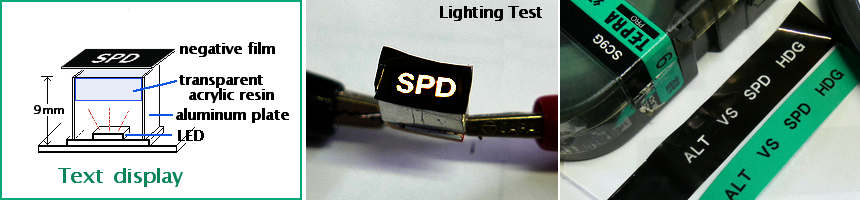
Text display
Character displays such as SPD and ALT have white characters on a black background. I made this.TEPRA is create labels by writing letters on tape. The mechanism is a thermal printer. Take out the negative tape with the traces of missing black letters, which is no longer needed and wound up. It is thin, curled and difficult to handle.
I devised it so that there is no unevenness in brightness when lighting with an LED backlight. First, create a distance from the LED, use a 0.2mm thick aluminum plate as a reflector around it, and rub the acrylic surface with sandpaper to make the light scattered. Even this was not enough, so I cut out the prism sheet that was used for the back of the LCD display and sandwiched it between them.
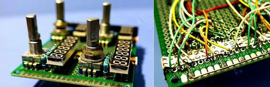
Universal board
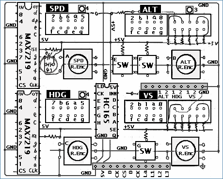 This is the layout of the main components on the board. A pull-up resistor, a current limiting resistor to the LED, and an IC capacitor are added to this. There are two connectors to the Arduino.
 When wiring to an IC such as the MAX7219, pasting a sheet of 6mm wide paper with the pin names written on it will reduce mistakes.
I used an 8x6cm universal board. The leg length of the 7-segment LED is used to match the height with the rotary encoder.
Display Settings
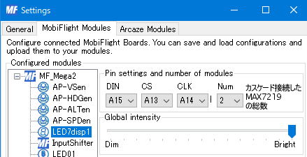
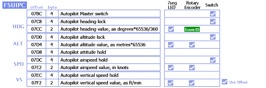
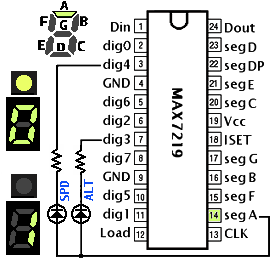
Four 7-segment LEDs are displayed using two MAX7219. I used FSUIPC's offset for setting Mobiflight.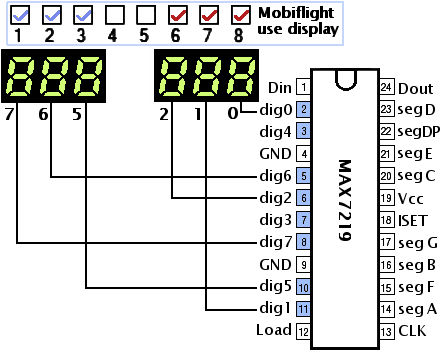 Connect the digit display between the 7-segment LED and the MAX7219 like this. Mobiflight's use display column says 12345678 from the left digit, but MAX7219's pin display says 76543210 from the upper left digit, which is often confusing.
 Here, the left 3 digits and the right 3 digits are used for different display. The two digits of dig3 and dig4 are not used.
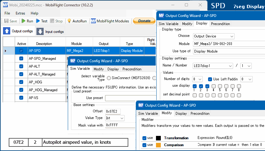
right justified display of numeric values
Since Mobiflight 9.6, the 7-segment LED display has been changed to support floating point numbers, so the right justification setting Use Left Paddin does not work well. 'Round' function is used to eliminate the fractional part.Rotary Encoder Settings
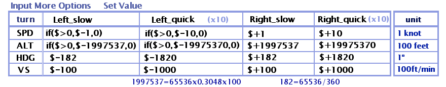
I can switch the amount of input change depending on the speed of turning the rotary encoder.The values in this table are taken from his Sebastian Möbius own AutoPilot explainer video. There is a difference of 10 times between slow and quick turning speeds. In addition, SPD and ALT are prevented from becoming negative values. VerticalSpeed is negative when descending.
 The display of HDG did not go well, and I had a little trouble.
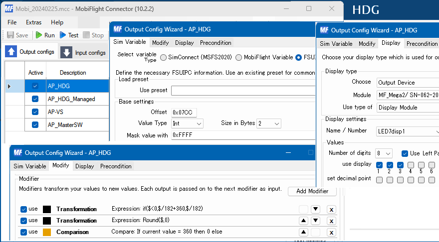
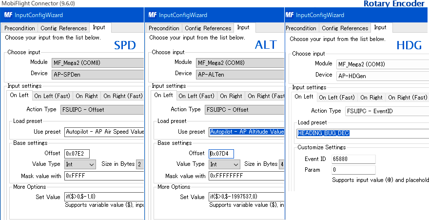
 The cause is that the azimuth data from FSUIPC is -32768~+32768 instead of 0~65536. It uses the most significant bit as the sign. So when I tried to set it to 315 degrees northwest, I got a negative value of -45 degrees.
Try various things, use EventID instead of Offset for encoder input. I set if($<0,$/182+360,$/182) to Transform of 7seg LED output.
 A Mobiflight>Forum post helped me find this out. I'm sure others have already asked this question, so I searched for it. Also, I realized again that the formula used for setting in it does not contain spaces. It cannot be separated by spaces for readability.
Mode selection
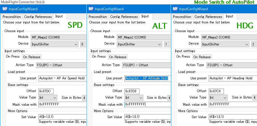
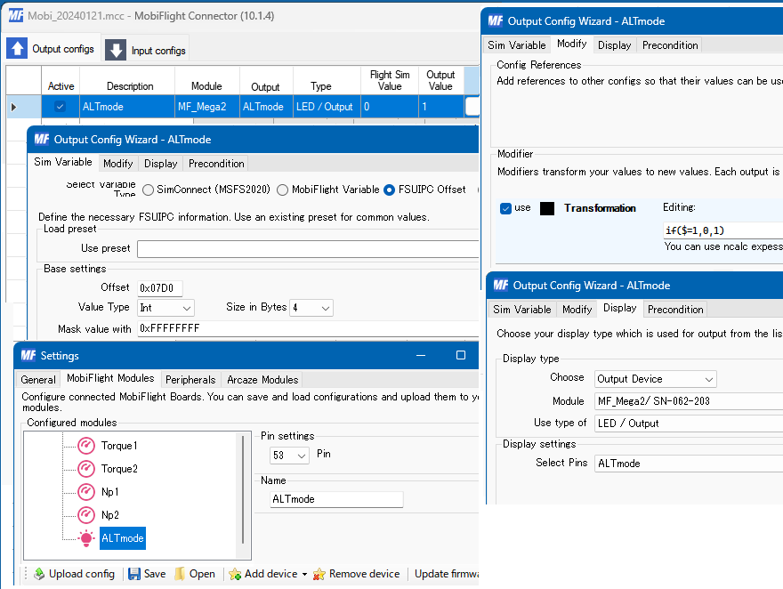
Managed mode and Selected mode are switched by pressing the switch in the rotary encoder. Then I turned on a small round LED to indicate which mode it was in.A push switch turns ON only when pressed and does not retain its state like a toggle switch. Use if($=1,0,1) in Mobiflight's MoreOption SetValue to keep the ON/OFF state like a toggle switch. If the value is 1, it will be replaced with 0. Otherwise (when it is 0) the value will be 1. With this, each time you press it, you can switch ON/OFF and keep the state.
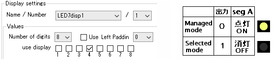
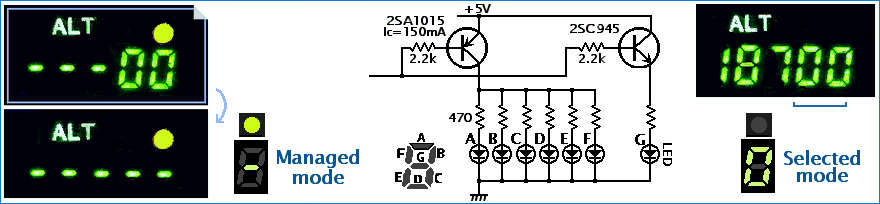
 There is no empty space on the right side of the number for the mode display LED, and it is above the number. I used the remaining dig3 and dig4 terminals of the MAX7219 for the driving LED circuit. Output 0 or 1 using seg A to turn the LED on/off.
 I didn't have enough space on the board to attach the output shift register 74HC595, and I didn't want to increase the number of connection lines with the Arduino, so I tried a little ingenuity. The resistance in series is to reduce the current required by the LED used and to match the brightness with the 7 segment LED.
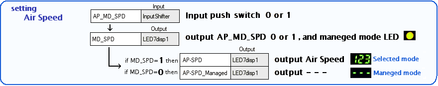
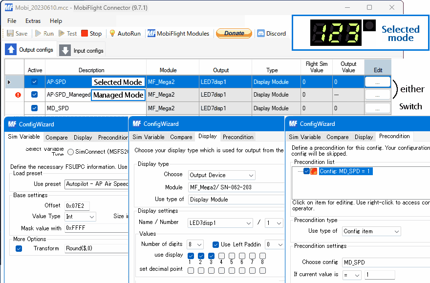
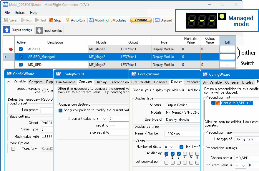
View Maneged Mode ---
When in Managed Mode, the 7-segment LED now displays three dashes --- instead of numbers.To switch the display, it refer to the value of MD_SPD. Based on this value, Precondition is used to switch between the two displays.
ALT 5 digits of management mode - - - - -display
The ALT display is 5 digits, but the setting is in 100 feet units, the lower 2 digits are fixed to 00 display. However, when I switch to management mode, the upper 3 digits are - - -, but the lower 2 digits remain fixed at 00. I thought of a way to fix this to - - when in admin mode.Since it is not dynamic lighting but direct current lighting, the current value to each segment is limited to 10mA. 10mA x 6 x 2 digits = 120mA
It was difficult to extract the signal from the MAX7219 and use it for this control, so I used the signal from the Arduino to switch.
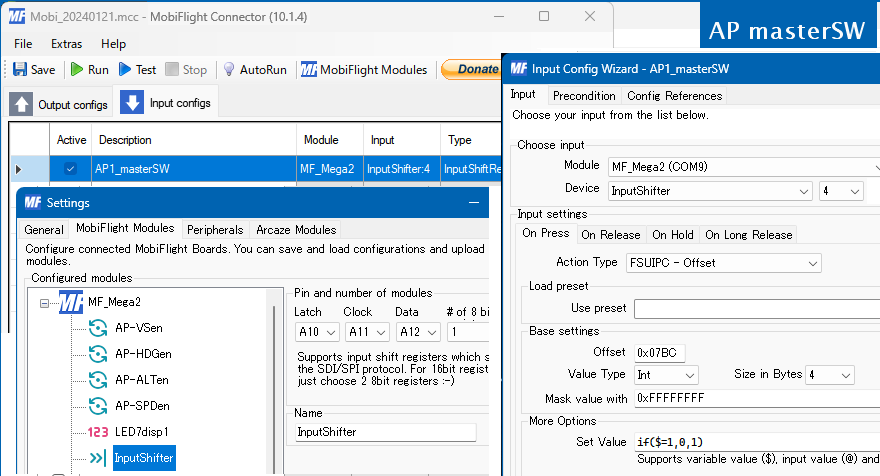
AP master switch
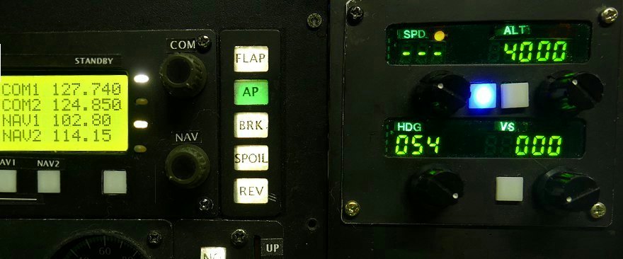
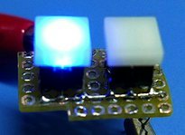 I also used her push button switch as the master switch to activate the AutoPilot. (The alternate action switch is too big to use here). Here too, if($=1,0,1) is used for SetValue to switch ON/OFF. The ON state of the AP is indicated by the blue LED built into the switch.