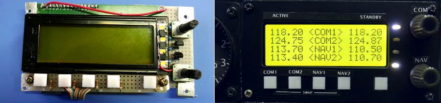
COM & NAV LCD display
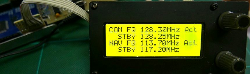
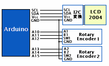
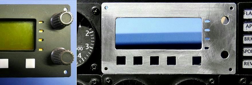
The frequency display used LCD 2004 with 20 characters and 4 lines. A compact 4-line display is possible.
This LCD2004 is convenient if the serial conversion board to I2C is mounted on the back side.
Arduino is a serial connection by I2C. Connect to his SDA and SCL terminals (D20, D21) of Arduino MEGA. This doesn't seem to change.
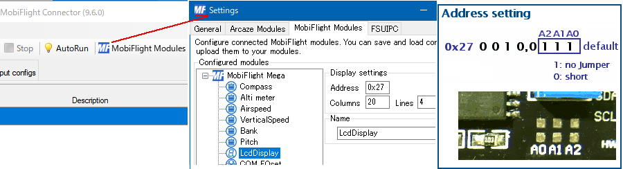
The serial address is 0x27, which is determined by the I2C conversion board attached to the display board. However, this address can be changed with jumpers A0, A1, and A2 on the conversion board. By changing the address, up to 8 I2C devices can be used for the same serial terminal.
(Depending on the I2C conversion chip, the serial address may be 0x37 instead of his 0x27)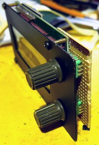
This LCD2004 is convenient if the serial conversion board to I2C is mounted on the back side.
Arduino is a serial connection by I2C. Connect to his SDA and SCL terminals (D20, D21) of Arduino MEGA. This doesn't seem to change.
The serial address is 0x27, which is determined by the I2C conversion board attached to the display board. However, this address can be changed with jumpers A0, A1, and A2 on the conversion board. By changing the address, up to 8 I2C devices can be used for the same serial terminal.
(Depending on the I2C conversion chip, the serial address may be 0x37 instead of his 0x27)
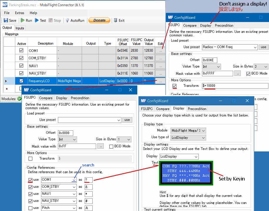
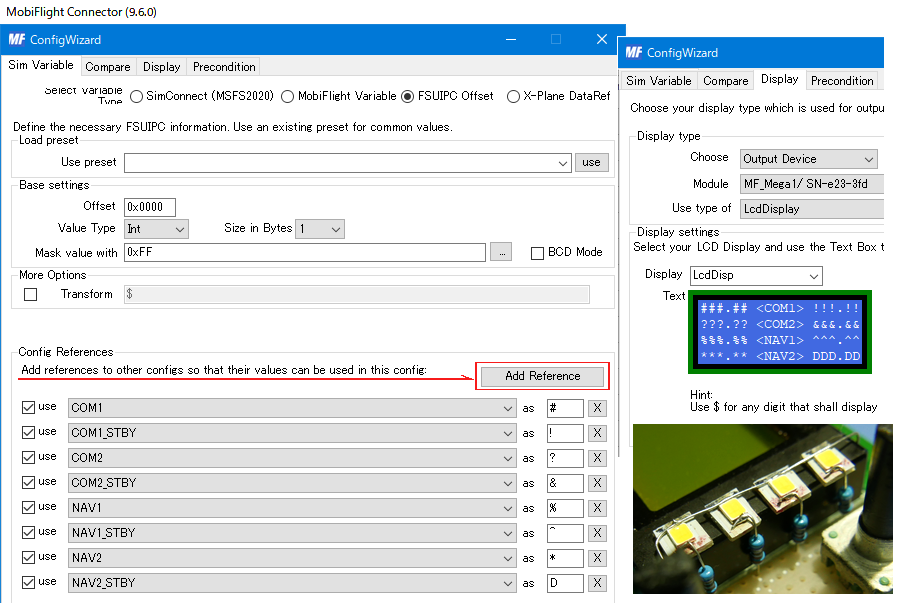
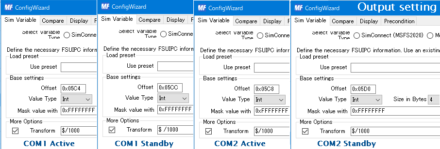
In the MobiFlight settings, first set the data received from FSUIPC in each of the four lines. No display settings are made for these 4 lines.
Display Setting Next, set the display settings separately. Select the LCD to be used in the Display type. Then, move the cursor to the display Text box on the blue background and enter the contents to be displayed with the keyboard to decide. (Use the Text Box to define your output)
The variable part is #& ? Enter only 5 digits with characters such as.
▶ Try to see if it is displayed on the connected LCD with test. At this point, no data is given because no data has been received from FSUIPC.
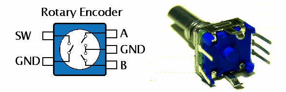
I used a rotary encoder for frequency input.
It is an interesting input device that is different from the variable resistor.
The connection is easy using the pull-up on the Arduino input side. No worries about chattering.
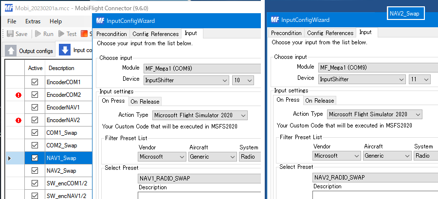
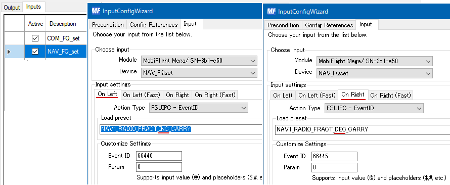
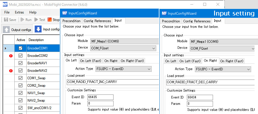
The frequency input is set on the Input tab of MobiFlight.
The rotary encoder has a part that raises or lowers the frequency depending on the direction of rotation,
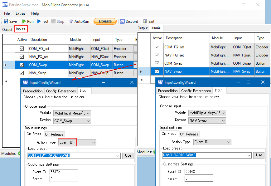
Set the part of the push button switch for switching between the ACTIVE frequency and the STANBY frequency.
We have assigned COM_STBY_RADIO_SWAP and NAV1_RADIO_SWAP to SW1 and SW2, respectively.
For some reason, the FSUIPC offset 0x311A didn't allow me to input the COM Stby frequency well, and now I'm using 0x05CC instead. Since this is an INT 4 byte, the number of digits will be large. If I use this, I can display the COM frequency in 6 digits, but since there is no equivalent to this in NAV, it is aligned with the 5 digit display.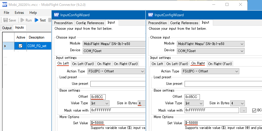
When MSFS2020 was running, turning the rotary encoder to change the COM Stby frequency causes Mobiflight to stop. Even if it RUN, it immediately became STOP.
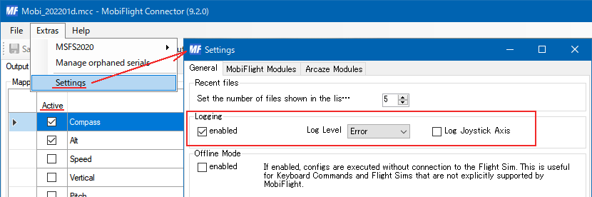
To find the cause of the error, I unchecked 'Active' at the far left of Output and Input to find out which one was the cause. It is often caused by hardware, but it may be a setting of Mobiflight. 'Logging' in 'Extras' Setting allows me to keep a record of when an error occurs.
In my case, it was recorded as "Error on config execution. Input string was not in a correct format."
I checked the Config settings but couldn't find any anomalies. So I opened the '.mcc' file in an editor and compared it to the part that works normally.
The clue is FSUIPC offset. What I found there was that the settings I had tried before should have been erased, but it remained. I've been remodeling it, so I'm trying various settings. It was recorded in the '.mcc' file even though I couldn't see it in the Config Wizard with the settings I wasn't using anymore.
Experiment with the Config settings to find out why Mobiflight hangs due to an error. If I cannot get out of the stopped state due to an error, I can get out of the stopped state by opening another .mcc file. To do this, you need to save the file under a different name and leave some different states, not overwrite it.
Use File>Example Sketch>EEPROM>eeprom_clear. I also set the serial port before that.
Then you can rewrite it to whatever you need.
 There was a time when I thought I had broken the Arduino board because it didn't recover at all. and
Even It has one more thing to do is hard reset it.
There was a time when I thought I had broken the Arduino board because it didn't recover at all. and
Even It has one more thing to do is hard reset it.
The Arduino MEGA 2560 has a reset switch button on the board. On the Arduino Pro Micro, connect the RST (reset) terminal to GND. While holding down the reset button, turn on the power. (Pro Micro does it a little differently)
With this, the unresponsive Arduino came back to life.

The rotary encoder has a part that raises or lowers the frequency depending on the direction of rotation,
Set the part of the push button switch for switching between the ACTIVE frequency and the STANBY frequency.
We have assigned COM_STBY_RADIO_SWAP and NAV1_RADIO_SWAP to SW1 and SW2, respectively.
For some reason, the FSUIPC offset 0x311A didn't allow me to input the COM Stby frequency well, and now I'm using 0x05CC instead. Since this is an INT 4 byte, the number of digits will be large. If I use this, I can display the COM frequency in 6 digits, but since there is no equivalent to this in NAV, it is aligned with the 5 digit display.
When an error occurs
What was working with this setting sometimes stopped working due to an input error from a certain time.When MSFS2020 was running, turning the rotary encoder to change the COM Stby frequency causes Mobiflight to stop. Even if it RUN, it immediately became STOP.
To find the cause of the error, I unchecked 'Active' at the far left of Output and Input to find out which one was the cause. It is often caused by hardware, but it may be a setting of Mobiflight. 'Logging' in 'Extras' Setting allows me to keep a record of when an error occurs.
In my case, it was recorded as "Error on config execution. Input string was not in a correct format."
I checked the Config settings but couldn't find any anomalies. So I opened the '.mcc' file in an editor and compared it to the part that works normally.
The clue is FSUIPC offset. What I found there was that the settings I had tried before should have been erased, but it remained. I've been remodeling it, so I'm trying various settings. It was recorded in the '.mcc' file even though I couldn't see it in the Config Wizard with the settings I wasn't using anymore.
Experiment with the Config settings to find out why Mobiflight hangs due to an error. If I cannot get out of the stopped state due to an error, I can get out of the stopped state by opening another .mcc file. To do this, you need to save the file under a different name and leave some different states, not overwrite it.
Arduino Reset
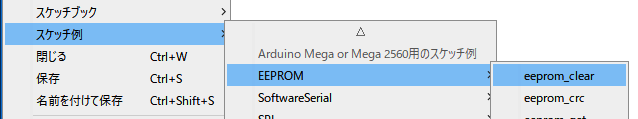
When the Arduino does not work well, the first thing to try is to use the Arduino IDE to erase the EEPROM.Use File>Example Sketch>EEPROM>eeprom_clear. I also set the serial port before that.
Then you can rewrite it to whatever you need.
There was a time when I thought I had broken the Arduino board because it didn't recover at all. and
Even It has one more thing to do is hard reset it. The Arduino MEGA 2560 has a reset switch button on the board. On the Arduino Pro Micro, connect the RST (reset) terminal to GND. While holding down the reset button, turn on the power. (Pro Micro does it a little differently)
With this, the unresponsive Arduino came back to life.
COM2 & NAV2
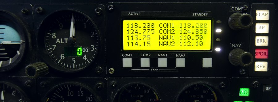
Show COM1,2 & NAV1,2
Until now, COM1 and NAV1 have been displayed on the LCD2004's 20-character, 4-line display, but I tried to display COM2 and NAV2 here as well. Since there are only two rotary encoders to be set, switch them and use them.I need 8 numerical displays, but until now only 6 could be set with the Config References in the Wizard. In Mobiflight 9.6, I can increase it with Add Reference as shown in the figure. Now I can easily display 8 numbers.
At this time, eight symbols such as #$%? are specified as variables, but characters such as ABCD can also be used here. However, if you do not avoid the 6 characters used for display such as COM NAV, the display will be confused.
Switch rotary encoder input
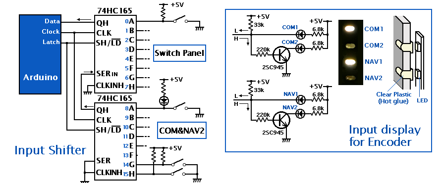
A rotary encoder pushbutton switch toggles between encoder inputs COM1 and COM2, and between NAV1 and NAV2 for him to choose. I attached four LEDs to the right side of the LCD to indicate which one is selected. A small indicator lamp with an elliptical hole on the surface. The elliptical hole is filled with hot glue from the back side like a lens. This selection display can also be included in the characters in the LCD, but COM1 and COM2 leave space to change to a 6-digit display. Since there are only two inverters for LED switching, I did not use TTL and configured with transistors.Use the four switches below the display LCD to switch between Active and Standby frequencies. I used it by cascading to the 74HC165 Input Shifter on the switch panel. The push button switch is a circuit that doubles as a pull-up and lights up an LED when pressed.
Offset 0x66C0
The point of how to switch rotary encoder input to change frequency is to use offset 0x66C0~66FF in FSUIPC. This 64-byte area can be used freely by user. I write the state of the switch here, reads it to know the state of the switch, and switches the input destination of the rotary encoder with Precondition Setting.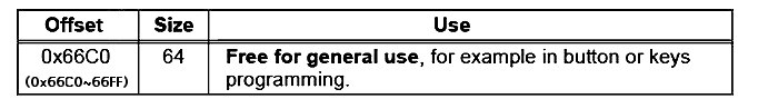
Switch Settings Wizard
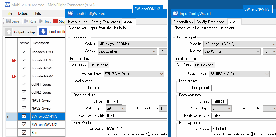
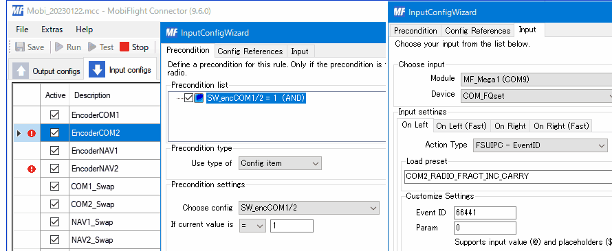
1. Toggles between 1 and 0 each time he presses the encoder pushbutton using if ($ = 1,0,1) it enter offset 0x66C0. (COM1 and 2 switching) To switch between NAV1 and 2, enter offset 0x66c1.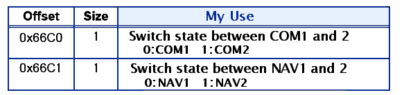
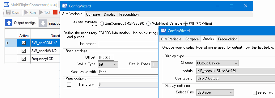
 2. Set the Output to read and use the value 0 or 1 of this offset.
 Using this, it now display which value (encoder input destination) with LED.
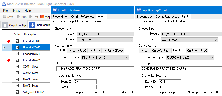
 3. SW_encCOM1/2= The value of 0 or 1 determines the input destination of the rotary encoder. Use Precondition for this.
 EncoderCOM2 is stopped when EncoderCOM1 is functioning, It is marked !.
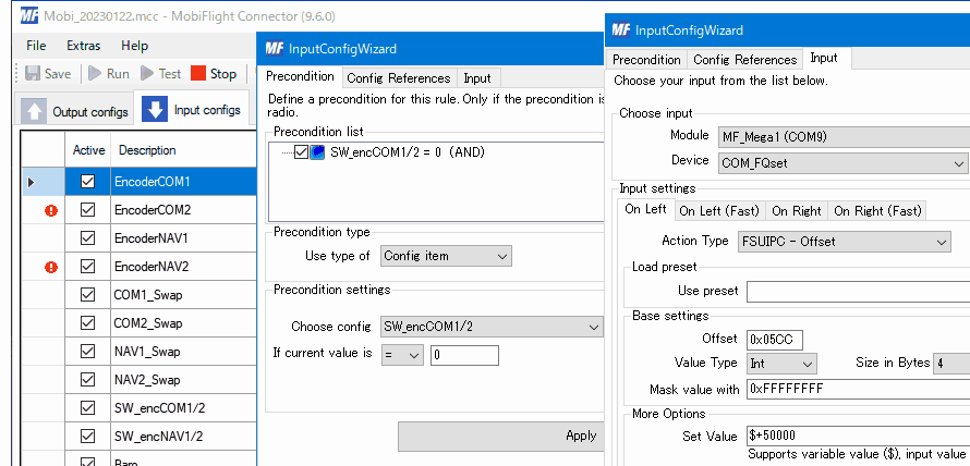 This is the 0 state of the switch, so the COM1 input is working. COM2 input is stopped.
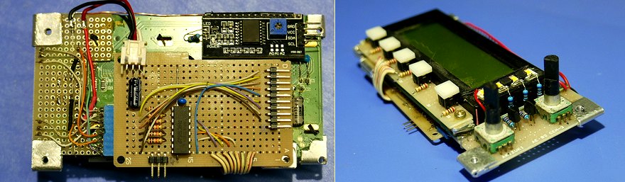 This is the back side of the LCD. The blue connector on the left is for the rotary encoder and its selection LED display, and HC165 in the center is Input Shifter. The 10-pin connector on the right is connected to Arduino.
Display COM frequency in 6 digits
Changed COM1 and COM2 to 6-digit display. NAV is 5 digits. I learned from Mr. Hortax how to use his 0x05C4 to 05D0 FSUIPC offsets to display 6 digits.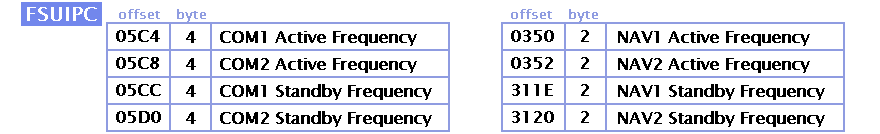 4 bytes can represent numbers from 0 to 4294967296. It seems that 8.33kHz units were introduced in the actual COM, but here it is set so that it can be changed in units of 25kHz (0.025MHz).
 Active and Standby swapping worked fine with Event ID in COM, but I had problems with NAV, so I changed Action Type to MSFS2020 like this.