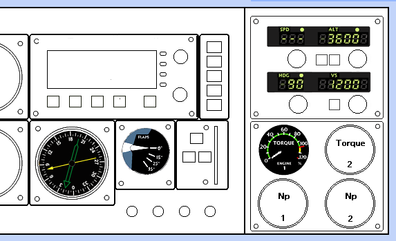
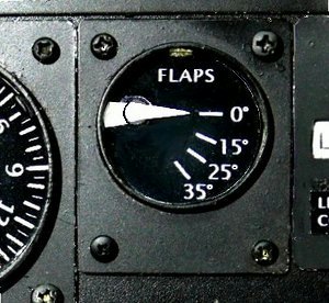
Flaps position indicator
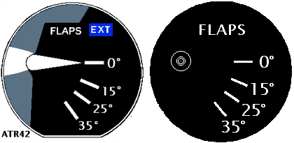
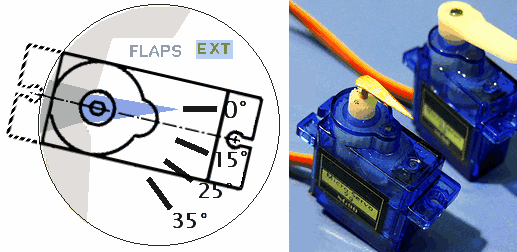
I make an indicator that shows the flap deployment status. I used the cockpit equipment of the ATR42 as a model. It is an indicator that allows you to visualize the flap status. The ATR72 has three display levels, but the ATR42 has four: 0°, 15°, 25°, and 35°.
The actual flaps are hydraulically operated, so it is slightly delayed compared to the flap lever man operate. It also shows the status.
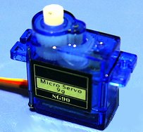
Servomotor
Mobiflight limits the number of stepper motors that can be connected to one Arduino to 10. I have already used up all 10, and the operating angle is small, so I tried using a Servomotor for this device.The rotation angle of the SG90 servomotor is limited to 180°, so the devices that can be used are limited. Also, although the operating voltage is 5V, the current seems to exceed a maximum of 1A, so power cannot be taken from the Arduino terminal.
The stepper motor's operating noise was barely audible, but the servo motor's operating noise was clear. Think of it as the operating noise of a flap hydraulic motor.
Setting up Mobiflight
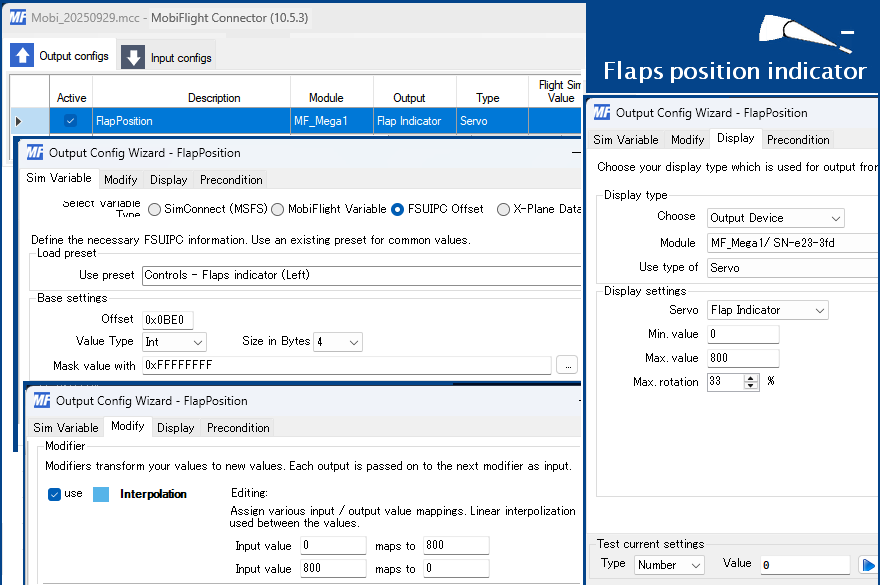
 Servomotor is to rotate counterclockwise. To make a meter, I need to rotate clockwise. I want this flap position indicator to rotate clockwise from the 0° position.
 To rotate in the opposite direction, you can use one gear, but I used the Modify setting in Mobiflight.
However, if you leave it like this, when the power is turned on, the needle will rotate 180° to the left and move to the 0 position. The operating range should be about 60°, so I set Max rotation to 33%. 180°x0.33=59.4°
Installing the servo motor
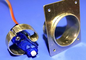 The diameter of the meter is small, so I wonder if the motor can be inserted even if it is slightly tilted. I will cut off the mounting tab on one side.
 There is also a protrusion around the motor shaft, so it seems that it will not work well with screws alone.
The included arm is called a servo horn, and it can be firmly fixed to the rotating shaft with screws. I think it is necessary when making robot arms. However, the fact that the head of the screw is visible in the center and that it can be fixed even though the rotating shaft is not in the center means that the needle may hit the outer frame due to a setting error. If it force the rotation to stop, the motor will heat up. Since I want to use it as a meter needle, no force will be applied. It is better to fix it lightly by fitting it in to prevent accidents.
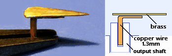 The hole in the motor output shaft is about 1.3mm in diameter and 6mm long. I cut a thick copper wire to a size that would fit snugly into it, bent and flattened the top end, and soldered a brass needle to it.
I will not make an EXT flag. This indicates that the flap valve is hydraulically commanding the flaps to deploy. If the EXT flag is displayed when the flaps are deployed, it means that there is a leak in the hydraulic circuit of the flaps.