Cockpit Factory :
Last update 11 Jan 2026 RMI
With Mobiflight and Arduino
This site is a production record of my cockpit equipment for Flight simulator.
I want to get data from Flight simulator
When flying a flight simulator with FSX, I am making various things to make it easier to see the altitude, direction of travel, speed, etc. instead of on the PC screen.It's a fun time to be able to make cockpit equipment such as meters by myself.
I looked into FSX flight altitude and speed data to see if I could make something that could be displayed on a 7-segment LED, separate from the PC display. Apparently, I found that FSX could provide various flight data from FSX using FSU IPC. I introduced it right away, but there is almost no detailed explanation about data acquisition. I was in trouble because I couldn't find a commentary site written in Japanese.
At that time, Mr. Kino, his FS senior who consulted and taught me various things, advised me to try using Mobiflight. Looking at the site, It was exactly what I wanted to do.

Mobiflight
Mobiflight Project's site https://www.mobiflight.com also has a tutorial that explains in detail from the beginning. The site is in English and German, so it was difficult to understand, but it was well written and I could get the information I wanted. It also supports MSFS2020.Additionally, Github has detailed instructions on configuring Mobiflight.
The Forum also has various uses for you. Not only the 7-segment LED but also the LCD display can be displayed,and with an analog meter by using a step motor. However, you need to attention to the version of Mobiflight used in the tutorial explanation. As the program is getting better and better, you may have a setting screen that is a little different from the explanation. (Please note the difference depending on the version even in my setting example)
The Mobiflight settings aren't a math application, but I'll list a lot of the settings I'm particularly confused about in his Config Wizard record.
Arduino
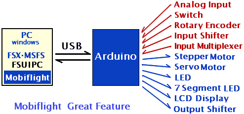
Windows PC has USB to connect external devices, but it is difficult to freely connect self-made devices with USB. Arduino is a one-board microcomputer that can be connected via USB, and has many I/O ports to connect my own devices.I am using Arduino MEGA 2560. I started with a small Arduino Pro Micro. But this has a small number of I/O, I think it is better to use MEGA2560, which has a large number of I/O from the beginning. Not compatible with Arduino Mini/Micro or Leonardo. Support for Arduino UNO seems to have started, but there seems to be a limit due to the small amount of memory that can be used.
If you connect to a PC via USB and run Mobiflight, you can input and output in-flight data from FSX. FSX requires FSU IPC.
However, Mobiflight 8.2 states that you does not need an FSUIPC if you uses the SimConnect WSAM offset instead of the FSUIPC offset.
 Mobiflight The latest Mobiflight 9.0 allows analog input. It seems that you can connect a variable resistor and input a voltage of 0 to 5V as a value of 0 to 1024. However, although it cannot be recognized and set as an FS input device as it is, it would be nice if it could be used for trimming and flap control. I will try it soon.
The output has increased Output Shifter. I can increase the number of output ports by performing serial-parallel conversion using 74HC595 .
In addition, Input Shiftregister (Input Shifter) has been added since Mobiflight 9.3. I can increase the number of input ports, which is convenient when connecting many switches. using 74HC165.
FSUIPC Offset
FSUIPC(Flight Simulator Universal Inter-Process Communication) extracts flight simulator data for us to use. The authors are Peter & John Dowson.The data is placed in memory. You don't have to be conscious of the memory address, but it offset shows where the aligned data is. It can be said that the position (relative address) expressed by the distance from the reference point. The size varies from 1-byte data to 8-byte data depending on the data type. List of FSUIPC Offsets
Stepper Motor
The step motor 28BYJ-48 was used to create the meters.I used the one with an operating voltage of 5V, but it should be noted that the current is a little high. When I actually measured it, when I connected five step motors, a current of 1.3A was flowing even when the motors were stopped. It is about 250mA per motor. You can only pull out from USB up to 500mA, so you'll need a separate power supply to connect more than one.
He also pays attention to the heat dissipation of the motor because the energy of this amount of electric current also leads to heat generation.
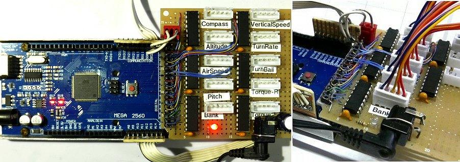
A driver board using ULN2003 was attached. This IC contains seven transistor arrays that increase the output. It's four transistor are used for one step motor, there are three extra transistors. Also, arranging a lot of these small driver boards makes the wiring unstable, so I made them into one board.

I'm doing this because I don't have a suitable connector to connect the cable to the Arduino. It is good for soldering flat cables, and can be firmly connected without wobbling by being sandwiched between aluminum plate cases. (There are no parts stores in Kyoto, so there are fewer opportunities to see and choose the real thing.)


